Setup
Bringing Your HomeKey-ESP32 to Life
Welcome to the exciting part! This guide will walk you through the process of getting your HomeKey-ESP32 device up and running. We’ll cover everything from downloading the firmware to flashing it onto your ESP32 and getting it connected to your network.
1. Download the Firmware
First things first, let’s get the brains of your HomeKey-ESP32 onto your computer. We provide pre-compiled firmware binaries, so you don’t need to worry about compiling anything yourself!
Visit the GitHub Releases Page: Head over to the official HomeKey-ESP32 GitHub releases page:
ReleasesDownload the Latest Release: Look for the “Latest release” tag. Under the “Assets” section, you’ll find several firmware files:
*.firmware.factory.bin: This is the file used to flash a new device for the first time. It contains the bootloader, application, and LittleFS filesystem all merged into one, ready to be flashed at address0x0.*.firmware.ota.bin: This file contains only the application firmware and is primarily used for Over-The-Air (OTA) updates.littlefs.bin: This file contains the web interface files and is also used for OTA updates of the filesystem.
More details on OTA updates can be found in the Updates Guide.
2. Connect Your Hardware
Before flashing, you need to connect your NFC module (PN532, PN7161 or ST25R3916) to your ESP32 development board.
- Using Jumper Wires: If you’re connecting the modules manually, refer to the NFC Module Wiring section below. Ensure you connect the correct interface pins (SPI for PN532, SPI + IRQ/VEN for PN7161 or I2C for ST25R3916) and power (VCC/3V3, GND).
- Using an Integrated PCB Board: If you have an Integrated PCB Board, connections are pre-wired. Simply select the corresponding hardware preset in the WebUI or Captive Portal.
2.1. NFC Module Wiring
Important
Both the ESP32 and the NFC module must share a common power supply and ground.
Note
The default GPIO Pinout scheme can be seen in the WebUI System section where you can also assign other pins to be used instead.
2.1.1. PN532 Module Wiring (SPI Mode)
Caution
The PN532 must be configured for SPI mode.
On standard red boards, ensure the DIP switch is set to 0 and 1 (left switch down towards 1, right switch up away from 2).
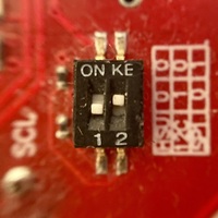
Default pinout table for ESP32 with PN532 over SPI:
| ESP32 Pin | PN532 Pin |
|---|---|
| VCC/3V3 | VCC |
| GND | GND |
| GPIO18 | SCK |
| GPIO19 | MISO |
| GPIO23 | MOSI |
| GPIO5 | SS |
2.1.2. PN7161 Module Wiring (SPI Mode)
PN7161 NFC controller communicate over SPI and require two additional control pins: IRQ (Interrupt Request) and VEN (Enable/Reset).
| ESP32 Pin | PN7161 Pin |
|---|---|
| VCC/3V3 | VCC |
| GND | GND |
| GPIO18 | SCK |
| GPIO19 | MISO |
| GPIO23 | MOSI |
| GPIO5 | SS |
| Configurable (e.g. GPIO4) | IRQ |
| Configurable (e.g. GPIO16) | VEN |
2.1.3. ST25R3916 Wiring (I2C)
Default pinout table for ESP32 with ST25R3916 over I2C:
| ESP32 Pin | ST25R3916 Pin |
|---|---|
| VCC/3V3 | VCC |
| GND | GND |
| GPIO5 | SDA |
| GPIO18 | SCL |
2.1.4. Integrated PCB Board Presets
When using an Integrated PCB or predefined layout, select the hardware preset in the Captive Portal or WebUI:
- @lollokara’s board (ESP32-C3) (SPI)
- CASmo-NFC (SPI)
- CASmo-NFC-MB-ETH (SPI)
3. Flash the Firmware
You can flash the firmware using command-line esptool.py or browser-based esptool-js.
Install esptool.py:
pip install esptoolConnect ESP32: Connect your ESP32 board to your computer via USB.
Identify Serial Port: Locate
/dev/ttyUSB0or/dev/ttyACM0(Linux),/dev/cu.usbserial-XXXX(macOS), orCOMx(Windows).Run Flash Command:
esptool.py --port YOUR_PORT write_flash 0x0 *.firmware.factory.bin
4. Wi-Fi Configuration & Initial Setup
After flashing, your HomeKey-ESP32 is ready for initial configuration.
- Connect to Wi-Fi Access Point: On first boot (or when no Wi-Fi credentials are saved), the device hosts an access point:
- SSID:
HK_{XXXXXX} - Password:
HomeKey$123$(this can be changed from the configuration page)
- SSID:
- Access the Captive Portal: If the operating system doesn’t automatically open the captive portal, navigate to
http://192.168.4.1in your web browser. - Configure Options:
- Wi-Fi & HomeKit: Scan and select Wi-Fi network, enter password, set 8-digit HomeKit pairing code, select HomeKey pass color (Tan, Gold, Silver, Black), and configure AP Access Point Password (
accessPointPassword). - Hardware Tab: Select NFC reader type (PN532, PN7161 or ST25R3916) and presets, assign custom NFC GPIO pins (including IRQ and VEN for PN7161), configure Ethernet settings, and see strapping pin restrictions on conflicting assignments. Override strapping pin restrictions if required by custom hardware (
overrideStrappingRestriction).
- Wi-Fi & HomeKit: Scan and select Wi-Fi network, enter password, set 8-digit HomeKit pairing code, select HomeKey pass color (Tan, Gold, Silver, Black), and configure AP Access Point Password (
- Save & Connect: Upon clicking “Save”, the captive portal submits configuration diffs and connects to your Wi-Fi network. On successful connection, the interface displays the assigned network IP address before closing.
5. HomeKit Pairing
The default HomeKit pairing code is 466-37-726. Once connected to your Wi-Fi network, open the Apple Home app, tap Add Accessory, and enter or scan the setup code.
6. Troubleshooting Common Setup Issues
- Failed to connect during flashing: Put board into bootloader mode manually (hold BOOT, tap RESET, release BOOT).
- NFC Reader Not Detected: Verify power connections and ensure DIP switch is set to SPI mode for PN532, or IRQ/VEN pins are correctly mapped for PN7161.
- Strapping Pin Errors: Assigning a strapping pin in the WebUI (chip-specific; e.g., GPIO 0 and 2 on standard ESP32) is rejected with an error unless
overrideStrappingRestrictionis enabled — use it only if your custom hardware requires it.